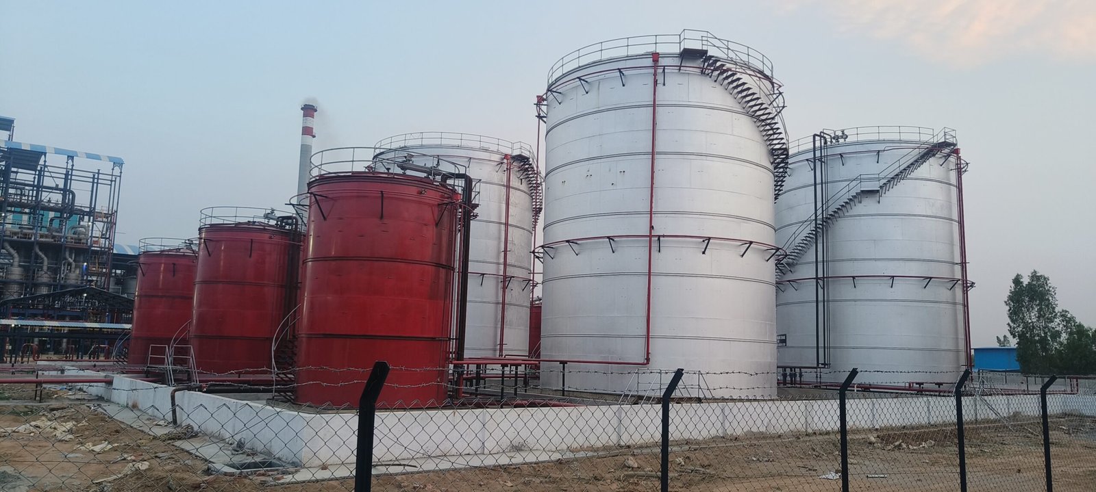
MVWS system is designed for a minimum spray density of 3 lpm per square meter of surface area. The design & installation of MVWS system shall also conform to the requirements of OISD.
The headers shall remain charged with water at the desired pressure. Whenever the water spray system operates, the discharge of water from the header shall result in a drop in pressure, which shall cause firefighting system pumps to come into operation.
The Medium velocity spray system shall work on wet pilot type detection system. A pipe network fitted with quartzoid bulb detectors shall be provided around tanks. This pipe network shall be kept pressurized by water tapped from the upstream side of a deluge valve provided at the riser of MVWS main. The downstream of the deluge valve is kept dry and shall be connected to a pipe network having strategically located spray nozzles around tanks. In case of fire, the quartzoid bulbs shall break thereby releasing the pressure in the detector network. This shall hydraulically open the deluge valve thus allowing water to be sprayed on the surface of the tank through Projector nozzles in the form of a solid conical emulsifying spray.
The trim of the deluge valve shall have manual emergency release as well as electrical actuation through solenoid operated valve and push button. A local control panel shall be provided for each deluge valve for local electrical actuation. It shall also be possible to remotely actuate the deluge valve from the Fire Alarm Panel located in the Control Room.
All necessary interface units required for remote control and remote annunciation shall be housed in the deluge valve local control panel.
All pipe shall be supported with superstructure and minimum head room clearance of 2.5 m from the finish floor level inside the storage section dyke area.

