
Automatic High Velocity Water Spray System
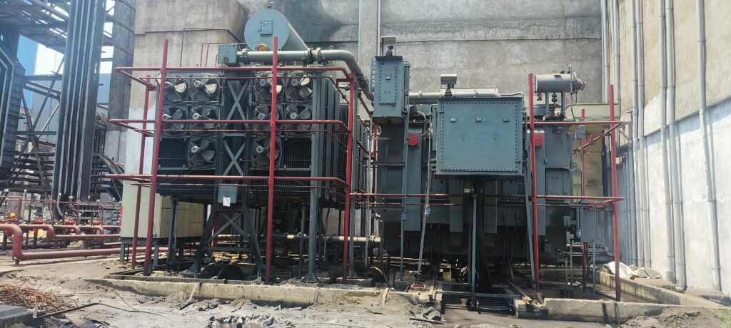
The HVWSS is designed for a minimum spray density of 10.2 lpm per square meter of surface area. The design & installation of water spray system shall also conform to the requirement of TAC. The headers shall remain charged with water at the desired pressure. Whenever the water spray system operates, the discharge of water from the header shall result in a drop in pressure, which shall cause firefighting system pumps to come into operation. The automatic HVWSS for transformer shall work on wet pilot detection system. A pipe network fitted with quartzoid bulb detectors shall be provided around transformer. This pipe network shall be kept pressurized by water tapped from the upstream side of a deluge valve. The downstream of deluge valve is kept dry and shall be connected to a pipe network having strategically located spray nozzles around transformers. In case of fire, the quartzoid bulbs shall break, there by releasing the pressure in detector network. This shall hydraulically open the deluge valve thus allowing water to be sprayed on to the transformer through projector nozzles / sprinklers in the form of a solid conical emulsifying spray. Pressure gauges shall be provided in the spray pipe and the detector network pipe respectively to indicate the available pressure. Deluge valve shall be provided with two pressure switches for following remote annunciation in the fire alarm panel located in the control room. Detector network operated Deluge valve open The trim of the deluge valve shall have manual emergency release as well as electrical actuation through solenoid-operated valve and push button. A local control panel shall be provided for deluge valve for local actuation. It shall be possible to remotely actuate the deluge valve from the fire alarm panel located in the Control room.
Automatic Fixed Foam System
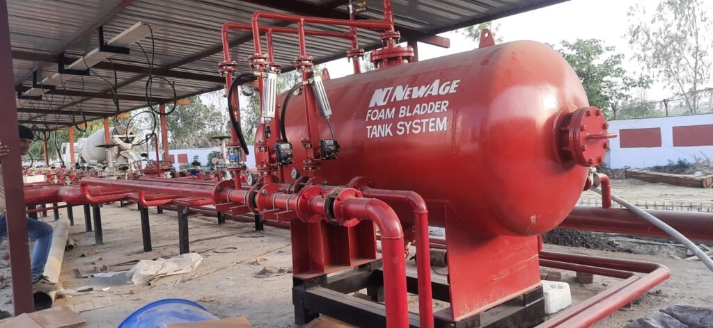
Fixed foam system is provided to suppress fire in absolute alcohol storage tanks and spill fire in dyke areas of storage tanks. The water required for foam system shall be taken from a branch of the hydrant main. Foam protection system shall be automatic in operation to extinguish fire inside tank and manual operated type for dyke area. The foam application rate to extinguish the fire is 5.0 LPM/ Sq M and minimum discharge time is 65min. The automatic foam system shall be actuated by receiving the signal from probe type heat detectors. The automatic foam system shall be actuated by receiving the signal from probe type heat detectors (Each tank shall be installed with 2 Nos min). Automatic foam system comprises of Solenoid operated deluge valve, isolation gate valves, and strainer, and inline inductor, foam making chamber, GI piping and probe type heat detectors. The water for the foam system shall be tapped from the nearby hydrant underground piping network. Deluge valve is the system control valve located at safe location. An isolation gate valve and a ‘Y’ type strainer will be provided on the upstream line of deluge valve. Pipeline up to the upstream flange of deluge valve will be filled with pressurized water. Inline inductor will be fixed in downstream of the deluge valve with a foam solution inlet. Foam maker cum foam pourer is fixed on the tank. GI pipe will be connecting between Deluge valve outlet and foam making chamber via inline inductor. Probe type heat detector shall be mounted on the roof of tank. During ‘fire’ condition, the probe type heat detector mounted on the roof of the tank detects the temperature inside the tank. Once the temperature of the tank reaches 58 Deg. C (136.4 Dec.F) it will send an electrical signal to deluge valve control panel. In turn the deluge valve control panel will operate the respective tank foam system by actuating solenoid valve mounted on deluge valve and open the foam solution line. The pressurized water will pass through the inline inductor where foam solution will be added in appropriate ratio. The foam solution mix will be converted into foam at foam making chamber and discharges into the tank. The foam discharged into the tank will form a blanket over the liquids stored on the tank and extinguishes fire by cooling and cutting oxygen supply to the source of fire. Foam solution should be stored in the bladder tank and further distribution to the inline inductor. All pipes shall be supported with superstructure and minimum head room clearance of 2.5m from the finish floor level inside the storage section dyke area.
Automatic Medium Velocity Water Spray System
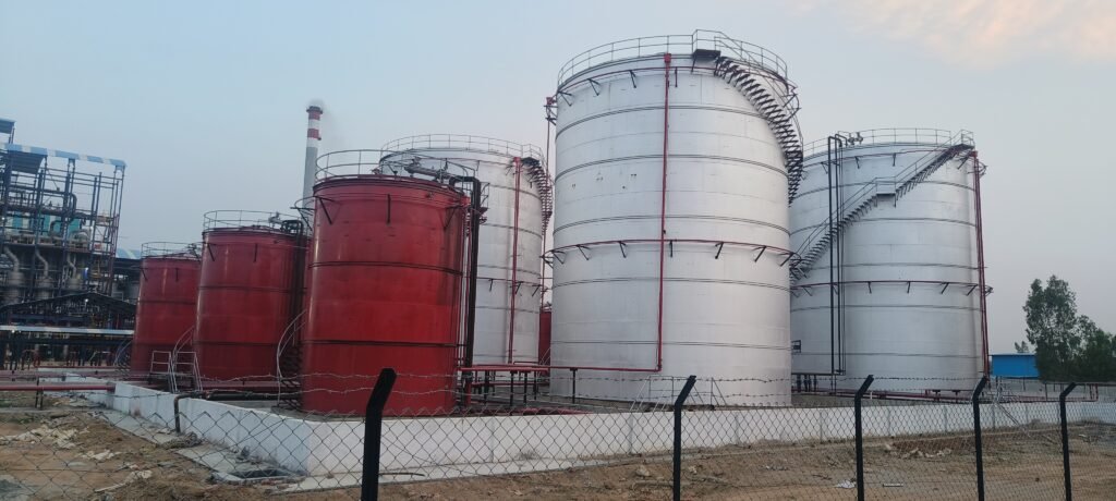
MVWS system is designed for a minimum spray density of 3 lpm per square meter of surface area. The design & installation of MVWS system shall also conform to the requirements of OISD. The headers shall remain charged with water at the desired pressure. Whenever the water spray system operates, the discharge of water from the header shall result in a drop in pressure, which shall cause firefighting system pumps to come into operation. The Medium velocity spray system shall work on wet pilot type detection system. A pipe network fitted with quartzoid bulb detectors shall be provided around tanks. This pipe network shall be kept pressurized by water tapped from the upstream side of a deluge valve provided at the riser of MVWS main. The downstream of the deluge valve is kept dry and shall be connected to a pipe network having strategically located spray nozzles around tanks. In case of fire, the quartzoid bulbs shall break thereby releasing the pressure in the detector network. This shall hydraulically open the deluge valve thus allowing water to be sprayed on the surface of the tank through Projector nozzles in the form of a solid conical emulsifying spray. The trim of the deluge valve shall have manual emergency release as well as electrical actuation through solenoid operated valve and push button. A local control panel shall be provided for each deluge valve for local electrical actuation. It shall also be possible to remotely actuate the deluge valve from the Fire Alarm Panel located in the Control Room. All necessary interface units required for remote control and remote annunciation shall be housed in the deluge valve local control panel. All pipe shall be supported with superstructure and minimum head room clearance of 2.5 m from the finish floor level inside the storage section dyke area.
Hydrant System
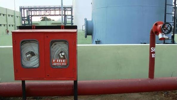
Hydrant type Fire Protection System essentially shall consist of a large network of hydrant valves – both indoor & outdoor. The hydrant network is divided into different ring mains, each serving various parts of the entire plant. All ring mains shall be suitably interconnected. The ring mains shall be provided with adequate number of isolating valves with valve chambers to obtain the best possible pressure at the seat of a fire. This will also enable isolation of any damaged portion of the network when required. The hydrant mains shall be buried piping, with external hydrants and risers for various areas & building. The hydrant network in the entire plant shall be sized and analyzed to ensure that about 7.0 bar (g) pressure is available at the hydraulically remotest point (as per OISD) in the system with the hydrant pump discharging at rated head and capacity. The velocity in the hydrant main shall not exceed 5 m/s. Each riser in the building is be provided with an Air Release valve at the highest point and a drain valve at the lower most point. The working pressure of entire firefighting system should be maintained at 8. 8 bar (g). All Firefighting system components and systems shall be designed for 1. 3 times of working pressure and the hydraulic test pressure shall be 1. 5 times of design pressure.